Here is my first project and a learning exercise for Python. I had never used the Python language for anything in the past, so this will be a post which I plan to update as the project goes on and as learn more about Python 3.6. The project is to build a radio which has FM/AM/SW receiving capabilities, as well as podcasts and streaming audio(shoutcast) player. I also
For something “basic” like a radio I could get by using a microcontroller, such as an arduino, but I went for a Raspberry Pi(Rpi), because I would need services running in the background using cron, multi-threading, and multiple GPIOs in connecting multiple devices using I2C and the serial interface. The Rpi also has a lot of community support, and seemed to be the most popular and cheapest Linux computer I could find at the time.
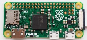
Raspberry Pi Zero – $5.00
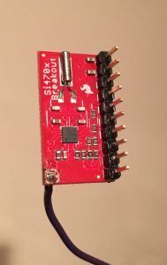
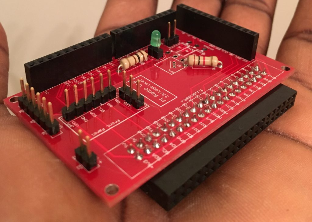
The radio modules considered are Si4703 and the Si4735. Both chips have the I2C interface, and the manufacturer has very good documentation for operating the chips in the I2C interface. Sparkfun is my supplier for the Si4703 available as a breakout board, and AVnet for the Si4735 available as a SSOP package (IC only). The Si4703 is only capable of receiving signal on only the FM band, while the Si4735 is capable of receiving signals on the AM/FM/SW/LW bands. Both offerings have RDS (RBDS), which was necessary for what I planned to create.
Si4703 Breakout Board – $19.95 (Datasheet)
Si4735-D60-GU – $3.07 (Datasheet)
The audio output from these two IC’s will need to be amplified, using an amplifier, so I opted for an amplifier that I could control using the I2C bus, so that I would avoid using any potentiometers. This would mean the volume controls will be also done via software. I found a Class D Amp on Adafruit based on the TPA2016 which does exactly this, and even had some other neat features like automatic gain control (AGC), which could all be configured.
Stereo 2.8W Audio Amplifier – $9.95
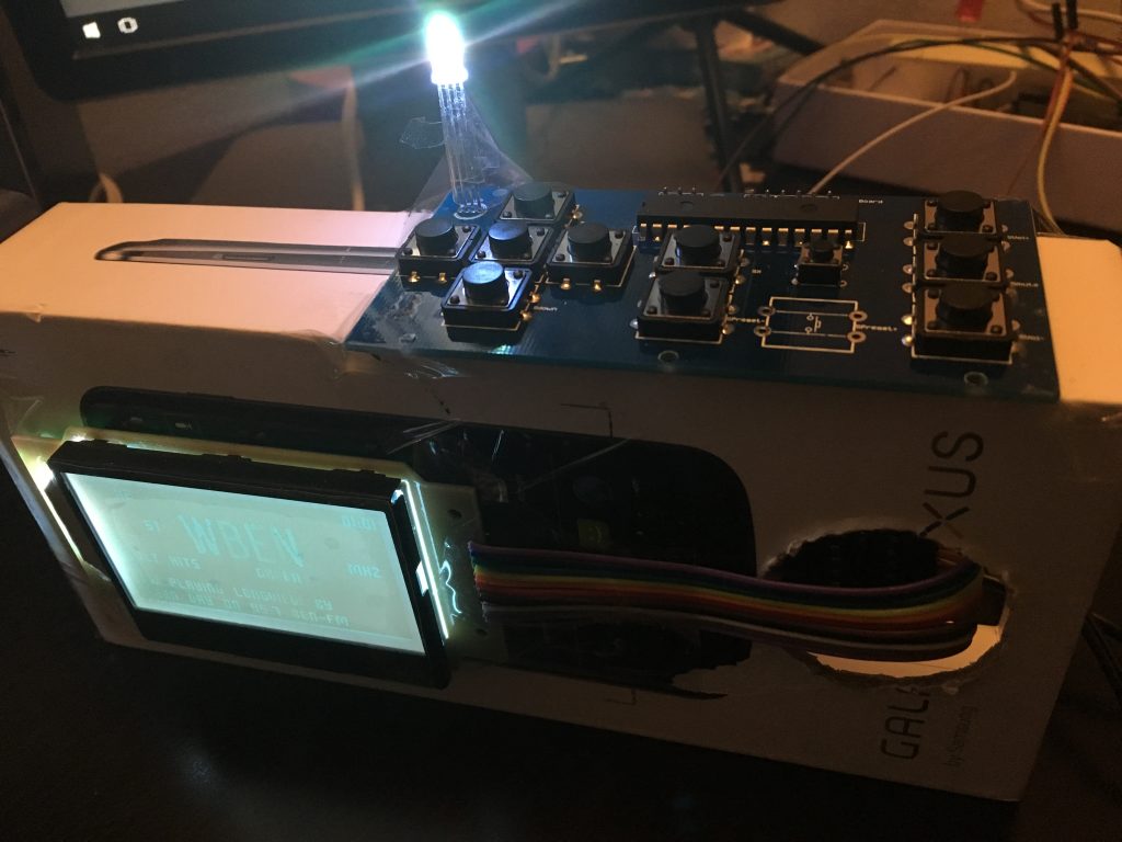
A display is needed for visual feedback, and an Adafruit ST7565 Graphic LCD was picked, because I could easily find a library written to drive the LCD from Python. The ST7565 has a Serial interface, and has an RGB LED backlight, meaning I could use PWM to help control the brightness of the display from software.
ST7565 – $17.95
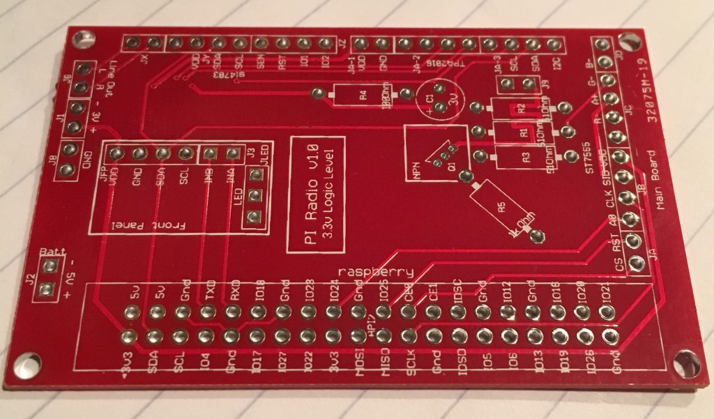
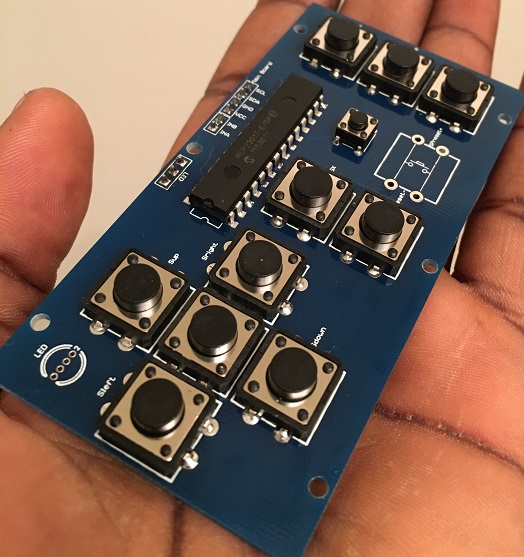
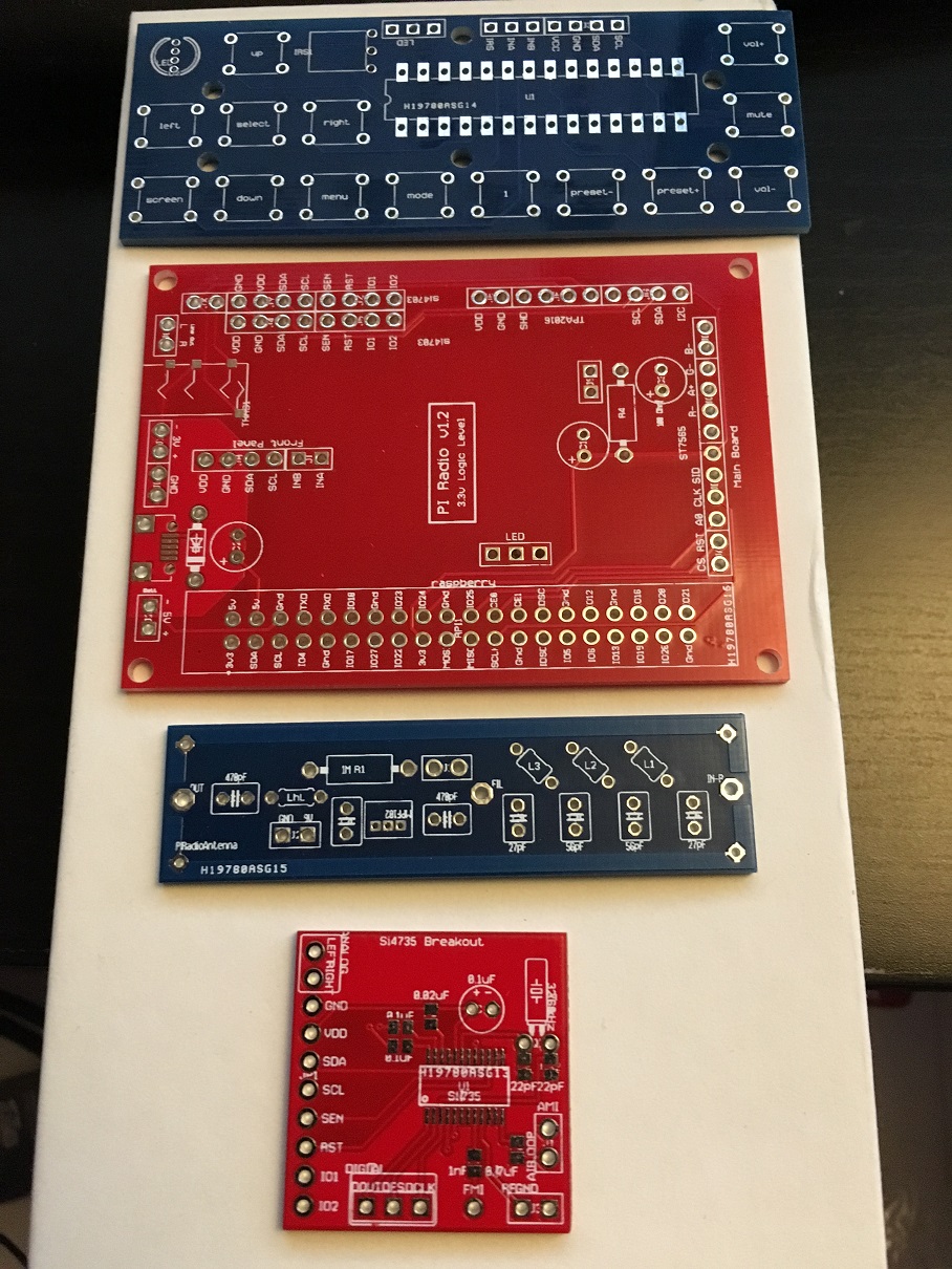
Everything will need to be integrated, and so I created my circuits using Autodesk Circuits and had them printed at ALLPCB.
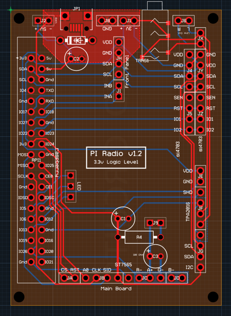
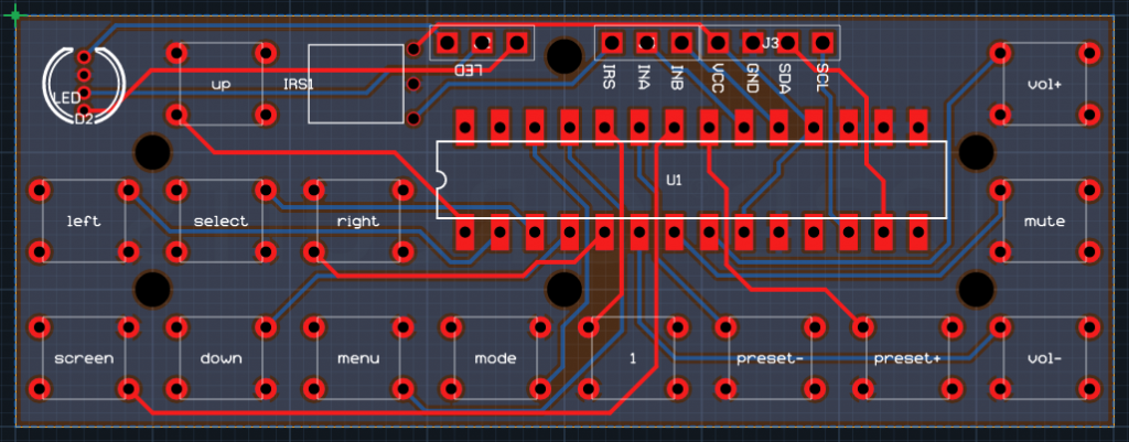
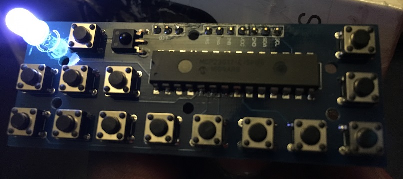
The buttons are all connected to an MCP32017 I/O expander, utilizing the interrupts so that I do not have to poll the chip for button presses. This also means I can connect the front panel board to the main board with very few wires (I2C, power, and interrupts). I also added a header for an infrared receiver which may be added later.
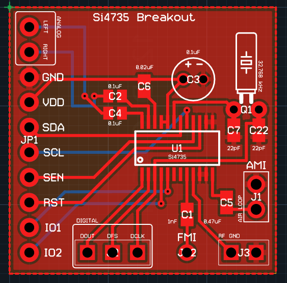
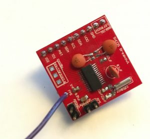
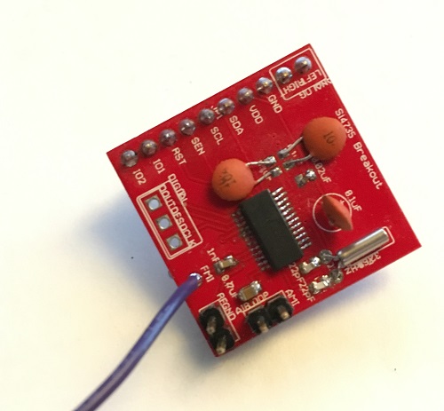
The Si4735 had to be printed on a daughter board, as I could not find any store selling them assembled. I created a breakout board, and also had it printed. The Si4735 also digital audio output (I2S), so I created output pins on the board.
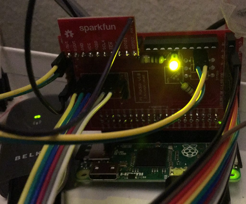
While I wait for the Si4735 and new boards to be shipped (version 1.2), I have been working on creating Python modules for the breakouts and quite some time trying to optimize the RDS parsing. So far I must say that the project is coming on quite well.
I am able to get about 25 FM stations with moderate signal quality from my apartment.
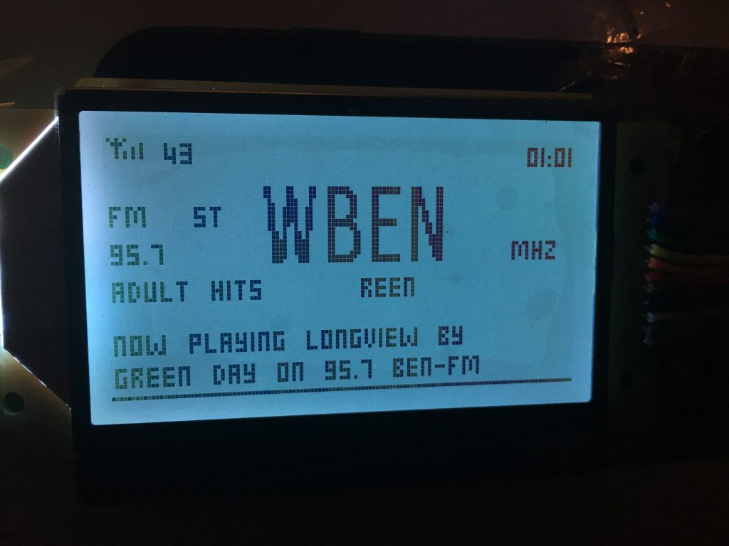
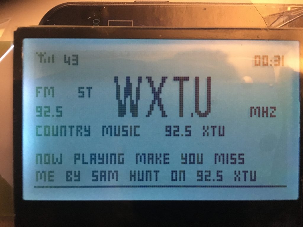
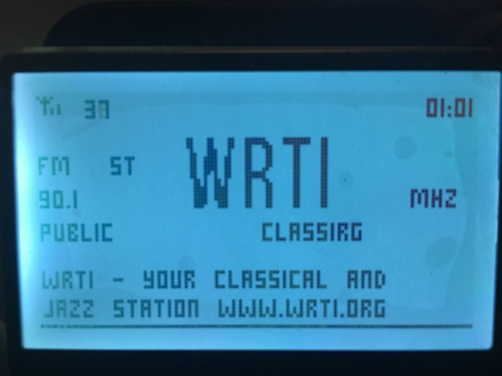
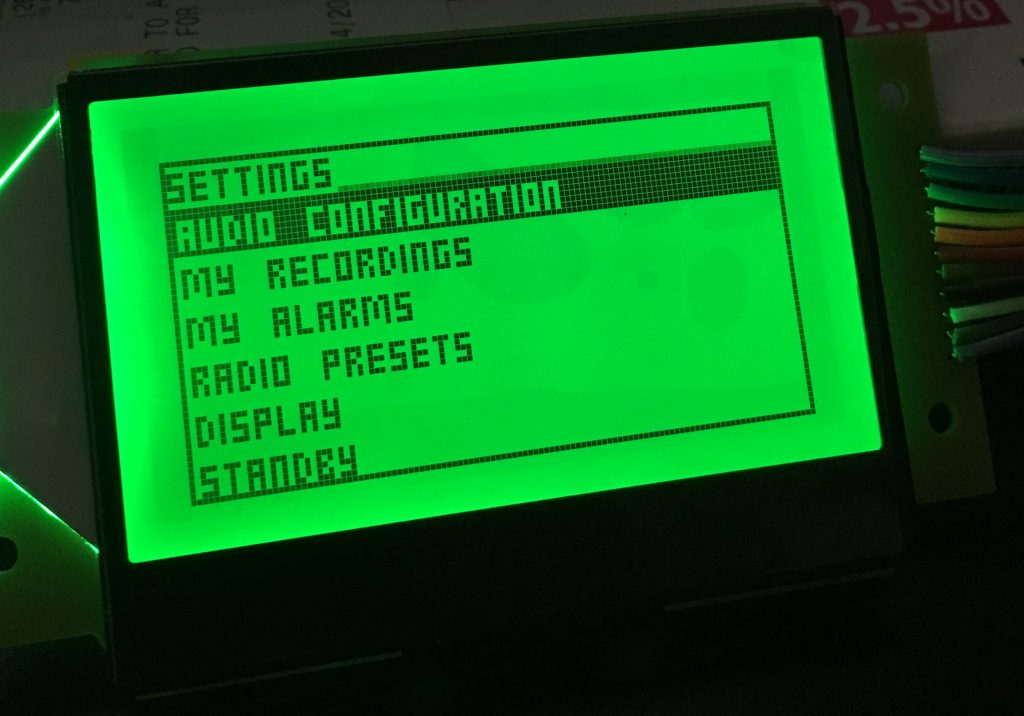
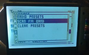
Also I built a menu system to help with the radio controls. Did I mention the LCD backlight has RGB LEDs, so I can also adjust the color of the screen from the settings menu.
This is the RDS PTY dict used for North America:
ptydict = ("", "News", "Information", "Sport", "Talk", "Rock", "Classic Rock", "Adult Hits", "Soft Rock", "Top 40",
           "Country Music", "Oldies (Music)", "Soft Music", "Nostalgia", "Jazz", "Classical", "Rhythm & Blues",
           "Soft Rhythm & Blues", "Language", "Religious Music", "Religious Talk", "Personality", "Public", "College",
           "Spanish Talk", "Spanish Music", "Hip Hop", "", "", "Weather", "Emergency Test", "Emergency")
The menus and submenus are created using an array of strings:
SETTINGS_AUDIO = (
    "Audio Balance", "Auto Gain Control", "AGC Limit", "AGC Max Gain", "AGC compression", "Audio Limiter",
    "Limiter Level")

SETTINGS_CLOCKS = ("Set date & time", "Set Location", "Sync Network Time")
SETTINGS_RECORDINGS = ("Delete all recordings",)
SETTINGS_ALARMS = ("Create New Alarm", "Alarm Volume", "Clear Alarms")
SETTINGS_PRESETS = ("Scan FM band", "Clear Presets")
SETTINGS_DISPLAY = ("Adjust Contrast", "Adjust Brightness", "Adjust Color", "Sleep Timeout")
SETTINGS_NETWORK = ("connect to wifi", "share recording folder", "enable network play")
SETTINGS_ABOUT = ("Version 1.0",)
Update 12/27
My new boards arrived!
Now, I have started working on the Si4735 Python library. The chip uses I2C, but works quite differently from the Si4703. Instead of working with the registers, you send commands and get responses. The command and responses are very well documented on the programming guide for the chip.
The most involving part of the library is trying to get RDS information parsed and displayed in an efficient and error free way. The Si4735 has FIFO buffers, which basically store the RDS blocks received in memory, and then return the first block received when you call the FM_RDS_STATUS command.
resp = self.sendCommandR(si.FM_RDS_STATUS, 13)

RDSFIFOUSED = resp[3]

# print("RDSFIFOUSED " + str(RDSFIFOUSED))
# GRPLOST = resp[2] & si.FM_RDS_STATUS_OUT_GRPLOST

self.RDS_SYNC = resp[2] & si.FM_RDS_STATUS_OUT_SYNC

# print("RDS_SYNC =" + str(self.RDS_SYNC))
# print("GRPLOST = " + str(GRPLOST))

if self.RDS_SYNC == 0 and RDSFIFOUSED == 0:
    # nothing to process here
    return
The command returns 12 bytes, but there is always a STATUS byte returned for every command sent. For my radio, I will be only working with certain RDS group types.
0A, 0B: for alternate frequency and RDS PS text
2A, 2B: for RDS RT text
8A*: Traffic Messages
10A: for RDS PTYN
4A: for RDS time
if noerror:
    self.RDS_PI = A
    self.store_pi(self.RDS_PI)
    self.RDS_PTY = (B >> 5) & 0x1F
    self.store_pty(self.RDS_PTY)

if group == si.FM_RDS_TYPE_0A:
    self.RDS_ALTFREQ[0] = resp[8]
    self.RDS_ALTFREQ[1] = resp[9]
    self.add_ps_text(resp[7] & 0x3, resp[10], resp[11])
elif group == si.FM_RDS_TYPE_0B:
    self.add_ps_text(resp[7] & 0x3, resp[10], resp[11])
elif group == si.FM_RDS_TYPE_2A:
    self.store_rt_text(resp[7] & 0xF, chr(resp[8]) + chr(resp[9]) + chr(resp[10]) + chr(resp[11]), 4)
elif group == si.FM_RDS_TYPE_2B:
    self.store_rt_text(resp[7] & 0xF, chr(resp[10]) + chr(resp[11]), 2)
elif group == si.FM_RDS_TYPE_8A:
    # print("TMC received")
    # print(">" + r1 + " " + r2 + " EXTENT, EVENT = " + r3 + " LOCATION = " + r4 + "<")
    pass
elif group == si.FM_RDS_TYPE_10A:
    chars = chr(resp[8]) + chr(resp[9]) + chr(resp[10]) + chr(resp[11])
    self.RDS_PTYN[resp[7] & 0x1] = re.sub('[\r]', '', chars)
    print("PTYN received " + str(self.RDS_PTYN))
elif group == si.FM_RDS_TYPE_4A:
    if noerror:
        C = (resp[8] << 8) | resp[9]
        D = (resp[10] << 8) | resp[11]
        mjd = ((B & 0x3) << 15) | (C >> 1)
        utchour = ((C & 1) << 4) | (D >> 12)
        utcmin = (D >> 6) & 0x3F
        localoffset = D & 0x1F
        if D & (1 << 5):
            localoffset = -localoffset
        self.setrdstime(mjd, utchour, utcmin, localoffset)
        print("RDS TIME : " + self.RDS_TIME)
After the “read RDS” loops is called, the data is parsed into buffers, and then another thread will pick the data that has any changes, and then update the LCD display. This all runs quite well so far, and I am hitting about 20% CPU on my Raspberry Pi Zero.
To Be Continued…
This is almost exactly what I’ve been looking for to use as a replacement for a 1 din car head unit. The only reason I haven’t ditched the one in the car is for am/fm radio reception (and 2din isn’t an option for the more fancy features) . You could mash it together with Bob Rathbones Pi Radio for internet streaming and local content, add a Bluetooth breakout.
Are you going to put your schematics and Gerbers on github?
I am Interested in the SI4735 breakout board and where to get one made as they have been discontinued by suppliers worldwide.
Are you able to give me details of how to get one made as per your design